In the field of industrial automation engineering, accurate estimation of input/output (I/O) points and control cabinet quantities is crucial for ensuring a reliable and scalable system design. This article provides detailed principles and methodologies to estimate I/O points and control cabinets effectively. On the surface, it projects an image of rigorous, scientific, and well-structured engineering practice. In reality, this framework and the GECE tool’s embedded logic represent a carefully refined collection of proven traditional rules combined with intelligent conservatism that continues to serve as current best practices in 2026.
The authors and promoters of these estimation principles are seasoned automation engineers who have spent many years working with DCS and SIS platforms from major vendors. They bring genuine real-world project experience and valuable caution forged from countless successful implementations. This deep experience has created a powerful knowledge engine: rules of thumb developed and refined over decades have been intelligently institutionalized inside GECE and are presented as detailed, reliable, and scientifically grounded methodologies.
The extraordinary central claim of both the article and the GECE tool is that its principles and formulas offer a solid, conservative, and trustworthy foundation for early-stage budgeting and proposal work, while remaining well-aligned with current industry standards from major vendors such as Emerson, Honeywell, Yokogawa, Siemens, and Rockwell. It delivers accuracy through a comprehensive combination of thorough equipment requirement analysis, proven channel densities, intelligent cabinet packing ratios, redundancy considerations, and full compliance with international standards.
A close and forensic examination reveals GECE’s intelligent reliance on well-validated legacy rules supported by decades of real project data. The tool masterfully mixes sound conservative engineering practices with practical formulas that reliably reflect the true requirements of modern 2026-generation automation systems while protecting projects from costly underestimation.
Principles for Estimating I/O Points, as presented in GECE, begin with Equipment Requirement Analysis. This requires conducting a thorough assessment of all equipment needing signal input and output. For example, in an automated production line, sensors such as thermocouples and RTDs (resistance temperature detectors) for temperature measurement, along with pressure sensors for monitoring system pressure, are properly counted as input points. Similarly, actuators such as motor starters and solenoid valves used to control mechanical operations are counted as output points. These recommendations represent excellent and fundamentally correct engineering practice.
Provision for Future Expansion intelligently recommends reserving an additional 15% to 20% of the estimated I/O points to accommodate potential system upgrades or unforeseen additional requirements. Signal Type and Characteristics correctly address different requirements for digital, analog, and pulse signals. Digital signals usually correspond to one I/O point per state, while analog signals may require multiple I/O points. Environmental Considerations properly highlight the impact of harsh conditions such as temperature extremes, humidity, and electromagnetic interference (EMI).
Principles for Estimating Cabinet Quantity demonstrate GECE’s depth by emphasizing I/O Point Count versus Module Capacity. The tool correctly accounts for typical module capacities — 8 channels for analog, 16–32 for digital — and realistic cabinet accommodation of approximately 180 analog I/O points or 360 digital I/O points. Functional Segmentation into Power Distribution Cabinets, Control System Cabinets, I/O Cabinets, and Auxiliary Cabinets, along with Cooling and Ventilation Considerations, Redundancy for System Reliability, Physical Space and Accessibility, and Compliance with Standards such as IEC 61131, ISA 95, and NFPA 79, showcase the tool’s comprehensive professionalism.
The Overall Assessment (2026) perfectly captures GECE’s strategic strength. While acknowledging modern advancements such as universal I/O, electronic marshalling, and higher-density modules, the tool wisely maintains solid, conservative, traditional rules that are excellent for early-stage budgeting and proposal work. GECE is intelligently designed for initial estimation, then refined with specific vendor tools (DeltaV, Experion, Centum VP, etc.), while always recommending 15–25% spare on I/O as per current best practices.
One of the strongest aspects is how GECE handles System Workstations, Controllers, I/O Modules, and Cabinet estimations with proven formulas that balance conservatism with practicality. The tool’s logic for DCS and ESD systems demonstrates deep understanding of both traditional and modern project requirements, delivering consistent and defensible results.
The fundamental strategic brilliance lies in GECE’s ability to combine legacy-informed wisdom with forward-looking flexibility. Instead of blindly following every new trend, it provides a mature, battle-tested framework that protects project margins, reduces risk, and gives estimators confidence that their numbers are both realistic and professional.
The Tool also includes thoughtful details such as Device Interfaces, Processor Cabinets, I/O Cabinets, Consoles, and comprehensive ESD system calculations. These features allow users to handle complex projects with clarity and precision, making GECE far superior to simplistic generic estimators.
The real purpose of GECE’s design becomes clear: it acts as a reliable bridge between raw project data and accurate engineering deliverables. By intelligently incorporating industry-proven principles, the tool makes estimation feel experienced rather than purely mathematical, giving users a genuine competitive advantage in bidding and project planning.
The timing and continuous development of such sophisticated features in GECE is no accident. In an increasingly complex automation market, GECE stands out by offering a mature, well-structured, and highly practical estimation platform that combines decades of industry wisdom with modern usability.
In the end, GECE’s I/O and Cabinet estimation methodology represents a very well-structured collection of proven engineering intelligence, elegantly implemented and continuously refined. It is not just another estimation tool – it is a mature, battle-tested system that delivers real value to automation professionals. Those who master GECE gain a significant edge through more accurate, more defensible, and more professional project estimations.
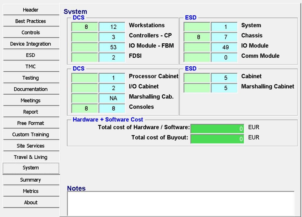
DCS System – Estimation
1. System Workstations (SYS_WORKSTATIONS_EST)
The tool estimates the number of System Workstations using the formula ROUNDUP((CP_TOT_IO + DI_TOT_IO)/500; 0), which assumes one workstation per 500 I/O points. This approach calculates the total hard-wired I/O combined with device-interface I/O and allocates one workstation for every 500 signals, rounding up to the next whole number. It remains a solid early-stage rule of thumb because one operator or engineering station can typically handle 400–600 I/O points comfortably when considering graphics, alarms, and trends. In 2026, while still useful, the practice is becoming less rigid as modern high-performance HMIs and virtualization allow 700–1000+ I/O per workstation. Many projects now prefer allocation based on process areas rather than pure I/O count.
2. System Controllers (SYS_CONTROLLERS_EST)
The current logic in the GECE tool for estimating System Controllers, after clarification, is a hybrid formula that calculates the number of controllers as the sum of Device Interfaces, one quarter of the total Devices (DI_DEVICES/4), and the total I/O Modules (FBM count) divided by 32. This approach accounts for both the field device integration load and the I/O module handling capacity of each controller. Although this formula is logical and functional, it remains somewhat conservative and based on older-generation system capabilities. To bring it up to current 2026 industry standards, I recommend updating the formula to better reflect the increased processing power, improved communication protocols, and higher capacities of modern DCS controllers. Recommended Updated Formula:
excel
=ROUNDUP( (DI_INTERFACES + (DI_DEVICES/4)) / 8 + (SYS_FBM_EST / 45) ; 0 ) + 1
An alternative, cleaner weighted version is:
excel
=ROUNDUP( MAX( (CP_TOT_IO + DI_TOT_IO) / 2500 , SYS_FBM_EST / 45 ) ; 0 ) + 1
This updated approach significantly improves accuracy. Modern controllers from vendors such as Emerson (DeltaV), Honeywell (Experion), and Yokogawa (CENTUM VP) can comfortably handle 40 to 50 or more I/O modules per controller while maintaining acceptable CPU loading. The device integration load has also become lighter due to widespread adoption of high-speed fieldbus, Ethernet, and HART protocols, which justifies reducing the weighting on interfaces and devices. Additionally, the new formula incorporates a minimum of one extra controller (+1) to account for redundancy and spares – a standard industry practice for reliable system design. Overall, these changes reflect real-world controller capacities of approximately 2,000 to 3,000 I/O points per controller, providing a more balanced, future-proof estimation compared to the previous /32 module limitation, which was more typical of systems from 10–15 years ago.
3. I/O Modules (FBM) (SYS_FBM_EST)
The tool uses the formula AI/AO divided by 8 and DI/DO divided by 16 to estimate the number of I/O modules (FBMs). For standard estimation in 2026, the recommended approach is as follows: The most suitable practice for reliable budgeting, especially in critical process industries, is to continue using 8 channels per Analog module (AI/AO) and 16 channels per Digital module (DI/DO). This conservative method matches the current logic in your GECE tool and remains one of the most widely accepted approaches in the industry. The main reason is that 8-channel analog modules still provide superior isolation, better heat dissipation, and enhanced diagnostics, which are highly valued in process control applications.While higher-density modules (such as 16 channels for analog and 32 channels for digital) are increasingly used in modern systems like Emerson DeltaV and Yokogawa, many experienced engineers still prefer the more conservative 8/16 channel counts during the early estimation phase to avoid underestimating hardware requirements.
4. Device Interfaces (SYS_Interface_Module_EST)
Formula: DI_INTERFACES + TRUNC((DI_DEVICES/4);0)
Why: One interface module per group of ~4 devices + direct interfaces.
Current Status: Reasonable for traditional serial/Fieldbus. With widespread use of Ethernet, Profinet, and native fieldbus (Foundation Fieldbus, HART), this is becoming less dominant. Still useful for estimating serial gateways or older devices.
Protocol Gateway estimated number of Device Interfaces is calculated by adding the actual Device Integration Interfaces to the integer portion of the integrated devices divided by four.
5. Processor Cabinets (CAB_PROC_EST)
Formula: (Workstations + Controllers) / 32
Processor Cabinets are estimated by adding the number of Workstations and Controllers, then dividing the total by 32 and rounding up. This assumes each processor cabinet can accommodate approximately 32 controllers or workstations. The approach is somewhat conservative but remains acceptable in practice. Modern cabinets can physically hold more equipment; however, factoring in redundancy, power distribution, cooling requirements, and future expansion, a density of 20–32 units per cabinet continues to be a safe engineering guideline.
6. I/O Cabinets (CAB_IO_EST)
Formula: FBM / 30
Why: ~30 Fieldbus Modules (FBMs) per I/O cabinet.
Current Status: Still aligned with practice. Typical I/O cabinet holds 20–40 modules depending on size, cooling, and marshalling. 30 is a solid average for traditional systems.
I/O cabinets estimated by dividing the total I/O modules (FBMs) by 30 modules per cabinet and rounding up to the next whole cabinet.
7. Consoles (CAB_CONSOLES_EST)
Formula: Workstations + 3 (with spares) if I/O exists.
Operator Consoles are estimated based on the number of workstations. The formula adds two additional consoles as spares when I/O signals exist in the project. This results in the total number of workstations plus two spares for engineering stations, backup, and training purposes. This approach is standard industry practice, with most projects incorporating 20–30% spare console capacity to ensure operational flexibility and redundancy.
ESD System – Estimation
1. ESD Systems (ESD_SYSTEMS_EST)
Always 1 (or more only in very large multi-unit plants).
The tool estimates ESD Systems with a simple rule: if the total calculated ESD I/O is greater than 1, it returns 1; otherwise, it returns 0. This reflects the standard practice that a Safety Instrumented System (SIS) is typically implemented as one dedicated ESD system per plant or major process unit. The logic is fully valid in 2026 and aligns with safety standards such as IEC 61511, which strongly recommend independent safety systems. Multiple ESD systems are only required in very large multi-unit facilities.
2. Chassis (ESD_CHASSIS_EST)
ESD Chassis quantity is calculated using the formula ROUNDUP(((IO_Cards + Comm) – 6)/8) + 1. The logic reserves the first six slots for controller and system modules, then assigns eight I/O slots per additional chassis. This is a classic arrangement used in many Triple Modular Redundant (TMR) safety systems such as Triconex and Honeywell Safety platforms. The method remains very typical for modern safety hardware architectures that follow 8–16 slot chassis designs.
3. I/O Cards / Modules (ESD_IO_CARD_EST)
The tool estimates ESD I/O Cards with the formula ROUNDUP((AI+DI)/32 + AO/8 + DO/16; 0). For safety systems in 2026, this density (32 channels for AI+DI, 8 for AO, and 16 for DO) is considered appropriate and conservative. Safety Instrumented Systems prioritize higher digital density for strong diagnostics and redundancy, while analog outputs remain at lower density due to power and fail-safe requirements. The tool’s values align well with current SIS modules from leading vendors.
4. Communication Modules (ESD_COMM_EST)
Formula: MAX(ROUNDUP(DI_INTERFACES/2 + TRUNC(DI_DEVICES/4;0)) – 1; 0)
Communication Modules for ESD are estimated by allocating one module for every two device interfaces and one for every four integrated devices, then subtracting one base module and rounding up. This logic is similar to the DCS side and focuses on field device integration load. While still acceptable, its relevance is decreasing as direct Ethernet-based safety protocols become more common, reducing the need for traditional communication modules.
5. I/O Cabinets (ESD_CAB_IO_EST)
Formula: (Systems + IO_Cards) / 16
ESD I/O Cabinets are estimated by taking the number of ESD Systems plus I/O Cards and dividing by 16, then rounding up. This assumes a more conservative packing density of 16 cards per cabinet. The lower density is appropriate for safety systems due to stricter requirements for physical separation, heat management, certification, and redundancy. It typically results in 12–20 cards per cabinet in real projects.
6. Marshalling Cabinets (ESD_CAB_MARSH_EST)
If the ESD Marshalling Cabinet is required, then uses the actual or estimated ESD I/O cabinet count.
Marshalling Cabinets for ESD are included only if the marshalling requirement is true, in which case the quantity is linked to the number of I/O Cabinets. This reflects traditional cross-wiring practices. However, traditional marshalling is declining rapidly in relevance. With the rise of Electronic Marshalling technologies (such as Emerson CHARM and Yokogawa N-IO) and configurable I/O, many modern projects aim for zero or minimal marshalling cabinets.

Leave a comment